At 47: 23 of the presentation ,Rossi says that he has a very short time to cool down the eletronics, any idea ?
This may link to my question below about where in the controller schematic the return electricity is thermalized. It's a long way from the pions however each piece of the puzzle helps shape the rest.
What is the patent application number?
Hi Mike,
WO 2017/1555220 A1. NASA patent application link:
http://e-catworld.com/wp-co...
Three more relevant NASA papers:
https://ntrs.nasa.gov/archi...
https://ntrs.nasa.gov/archi...
https://arxiv.org/abs/1704....
All from Bob's MFMP page:
https://steemit.com/steemst...
BTW they discovered, in the attached papers, loading the high Z, high proton count, host matrix with H did not produce any results. Seems a nucleus with at least 2 nucleons, held together with Pions carrying and exchanging the redundant strong force is required for this deuterium fusion trigger effect to work. I find that VERY interesting.
Here is how the redundant strong force is carried and exchanged between 2 nucleons. Very exposed Pion there. Not protected from photon impacts by the Coulomb barrier. Wonder what would happen if some of the strong force carried by the Pion was transferred to and carried away by progressive photon impacts on it? Would the strong force gradually reduce, slowly increasing the nucleus radius, eventually allowing the nucleons to come out and play with their neighbors?
Lots of papers on photons and pions.
Thanks, I'll check these papers out as soon as I get time.
Here is the killer statement in the 2nd NASA paper, top of page 16:
https://ntrs.nasa.gov/archi...
"It can be seen from both sets of data the photon stimulation technique with deuterated materials created new isotopes with 100 percent reproducibility."
Guess what?
The photon triggered LENR reaction DID NOT work with H loaded materials. Why? Because the H nucleus has no Pions carrying and exchanging the strong force with other nucleons.
So no Pions for the photons to hit and take away strong force energy.
"3.1.2 Control Tests
Tests performed with hydrogenated materials (instead of deuterated) ErH3+C36H74+Mo and HfH2+C36H74+Mo showed that no new spectral lines were created from exposure.
Tests were also performed with non-gas-loaded erbium and hafnium, which also showed no new spectral lines were created, as expected."
Seems the Cat is out of the Bag, so to speak.
Photon triggered LENR, with nucleus of at least 2 neuclons, which I believe includes the QX, is very real and probably coming to a LENR lab real soon, if not already there.
Seems they did not consider photons impacting the Pions and carrying away some strong force KE.
"4.2 Mechanisms Considered
There are several plausible mechanisms for the observed neutron activations:
(1) Deuteron photo dissociation:
Photo dissociation was carefully considered, as this is an obvious source of neutrons. However, the beam end-point energy was shown to be below 2226 keV (deuterium photo dissociation threshold) by the water tank ionization chamber method. Based on this method, the beam was operated below the photo dissociation threshold, and therefore is excluded from being the source of neutrons.
(2) Electron capture:
Parent metal capture of electrons was also considered. Certain radioisotopes can be formed via electron capture. However, if electron capture would have occurred, then these spectral lines would have been obvious when exposing either the hydrogen-loaded materials or the bare, non-gas-loaded metals. No such activation was observed. Activation only occurred with those reactants containing deuterium.
(3) Gamma-n processes:
Photo neutron reactions were also considered. Classic photo neutrons are not the cause of the activation of the Hf, Er, or Mo in the deuterated cases. First, the gamma energy is several MeV too low to cause photo neutrons in these materials. Second, if photo neutrons were at work they would have occurred in both the hydrogenated and non-gas-loaded materials, but these reactants did not show activation.
(4) Gamma-metastable processes:
As mentioned, 180mHf was created in the deuterated cases where hafnium was included. It was postulated that 180mHf may have been created by the gamma energy exciting 180Hf to the metastable condition. However this is not the mechanism, as again it would have occurred for either the H-loaded or non-gas loaded hafnium specimens exposed to the beam under the exact same conditions, but these metastable radioisotopes
did not appear in those instances.
(5) Mossbauer effect:
Upon gamma ray excitation of nuclei that are embedded in the lattice, and if the recoil energy is not sufficient to generate a phonon, there is the finite probability that the entire crystal recoils, rather than an individual nucleus, resulting in essentially a recoilless emission of gamma-photon. This process is called the Mossbauer effect. However, it is well known that the Mossbauer effect results in milli-electron-volt energy levels, which are irrelevant in comparison to the energies being considered in this study.
(6) Three-body interactions:
Theoretically, one can postulate an event in which fluorescent photons arrive at a target nucleus also being exposed with a photon having energy very close to photo dissociation, together exceeding the photo dissociation energy. Aside from the typical exceedingly low probability of a three-body interaction, the highest fluorescent photons from the present experiments are in the 50 to 60 keV range.
(7) Contribution from external sources:
Activation was only found when D-fuel was included in the specimens. This would argue strongly against specimen contamination from external sources. Regarding potential contamination, the gamma energy spectral lines were specific for the radioisotopes identified in the paper and were not those for lead, thorium, or radon radioisotopes, and were further confirmed with half-life determination.
The Standard Model of particle physics, incorporating the electromagnetic, weak, and strong forces may provide for other possible mechanisms that account for the reactions observed herein. However, discussion of those is beyond the scope of the current experimental work."
E48: I mean, there are a LOT of papers on "interaction of photons and pions" going back at least to the early 60's. Odd that the NASA group did not consider it as part of a possible mechanism. Do you have any specific citations on photons mediating the strong force? Perhaps researchers have only seen scattering or other signals from photon/pion collisions but have not been able to experimentally correlate that to changes in the strong force, even though it certainly seems to be something that could happen in that ball park. Seems like it might be a question of how long the pions are exposed and how much "attraction" (force? energy? momentum? desire?) they have on their paths between nucleons, relative to the impacting photon energy.
Very interesting, I suppose they did not all ready consider Carl Oscar’s theory although interestingly the last paragraph may be alluding to it.
I was once wondering if the Mossbauer effect plays a role in translating the nuclear energy if the crystal is small enough perhap phonons are genetated in adjacent and connected crystals and through coupling or resonance or some kind of internal conversation into ejection of the Hydrogen ions on the outer surface . Ni61 is a Mossbauer isotope.
Submitted to JONP:
Engineer48
Your comment is awaiting moderation.
December 13, 2017 at 9:14 PM
Dear Andrea,
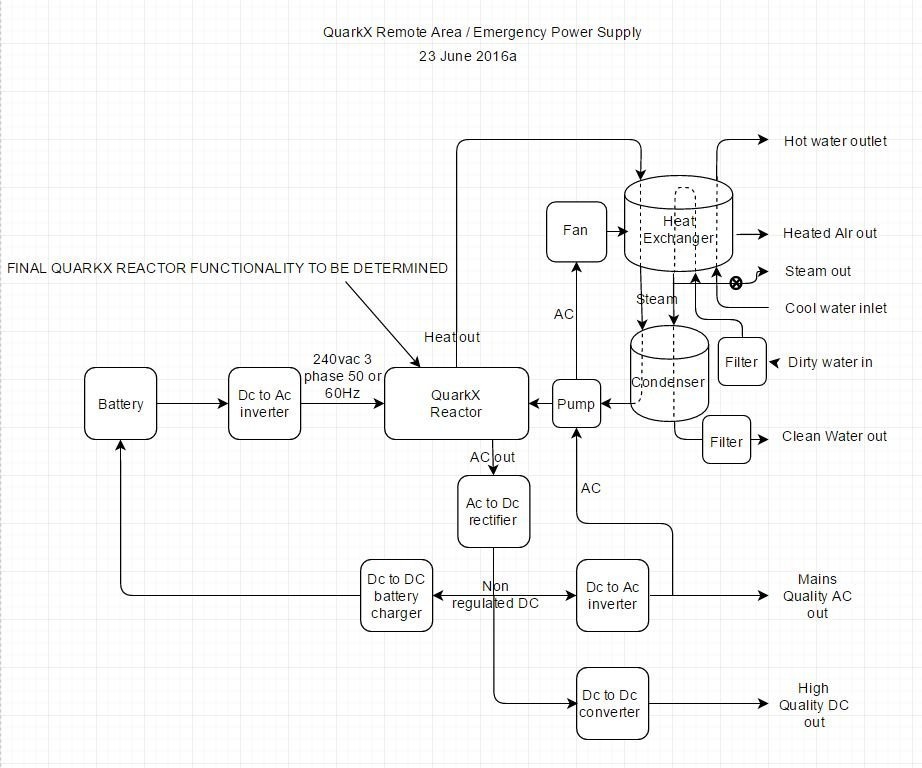
If you recall our discussions in June 2016 about the QX reactor based Remote Area / Emergency power plant that I planned to build in 8ft containers.
Please refer to the discussion on ECW:
https://e-catworld.com/2016...
and the plant schematic: https://uploads.disquscdn.c...
I’m still keen to move forward with this project as I believe these plants can deliver life saving energy and clean water to many of the world’s population that are energy and clean water poor. I’m sure many storm damaged areas of the planet would also benefit from drop in QX reactor based power plants delivering electricity, clean water, hot water and steam.
Back then you shared the QX could output 10% of total energy as electricity and that you had a goal to achieve at least 20% by product launch. Is the 10% still available and have you achieved the 20% goal?
I look forward to receiving my 1st QX reactor and building a pilot plant.
Too bad Rossi did not answer your question about the potential electrical output as it would have been good to know if it is now possible to get more electrical output:
Andrea Rossi
December 13, 2017 at 9:36 PM
Engineer48:
We are working very hard to start the massive sales of the industrial E-Cats within 2018. It will be hard, but we are struggling.
Warm Regards,
A.R.
Let's hope that Rossi's final statement: "It will be hard, but we are struggling" is the result of his familiarity with English, rather than he is really "struggling".
Well, they may be "struggling", but I don't think that's what he meant. It's like his use of the term factory. May be well and good in Italy, but not so much in the U.S.. I would never call my 30x40 shop a factory even at 5 times it's size.
48,
Just order it and see what happens,
He can only say yes or no.
If he says yes, you get an idea of
$$$ and delivery and what utilities are needed to make it operational.
Eng48,
In a reply to Manuel Cilia a few days ago, he states that he has no licensees in Australia.
I don't know what role Roger Green ( E-cat Australia) now plays.
But why not mount a case to trial and test Ecat QX boilers at that power plant you had commercial relations with.
If the power company can contribute some resources, you may have the first pilot site in the world.
Hi Vinney,
I emailed Roger Green last year. Told me he passed his Australian license back to Leonardo.
Said he was a non exclusive agent for Leonardo.
I'm also a non exclusive agent for Leonardo. Have an order for a 10kW QX reactor with min 10% electricale energy output. No money paid, awaiting on the invite to come, inspect and test. Then money changes hands.
48,
That is great, were you given any idea as to when?
Remember IH fiasco, complete your due diligence before nickel 1 changes hands.
It would be interesting to see a discussion here on how the thousands QX reactors are going to be mounted.
Rene said a year ago that they would be dimples on steel sheeting or pipes.
That's fine if a lot of them were controlled simply by EMF, RF or just heat.
But it appears a vast number of them will need an electrical source.
Rene recently said they most likely be spaced out on thin concrete slabs or pipes.
I would add a number of different shape ceramics.
Both concrete and ceramics can easily accommodate thousands of tiny wires in the manufacture process.
Any engineers here have any better configurations or base material compositions.
How would a 10MW boiler be efficiently configured.
Thinking about it, the thin concrete slabs or pipe segments (semicircular segments) that will fit into boilers, and similar high temperature ceramic elements, where the thousands of wires and reactor housings are (set in case of concrete) baked in.
These intricate housings contain no sensitive IP and can be manufactured by third parties.
Rossi's robotized lines would simply install the keyed reactors in these keyholes (already set into the concrete or ceramics) by the thousands. As can be expected by a newer technology, these tiny reactors can also be removed when spent, and replaced. These concrete and ceramic sections can be re-used up to 10 or 20 times (although highly dependent on sustained temperatures reached and duty cycle).
The other manufacturing line Rossi would want to maintain 'in-house' is the manufacture and preparation of the nickel, and the insertion of the mixture into the housing tube.
This would require pharmaceutical level production machinery, easily customisable from machines already built for other customers.
There is nothing outlandishly difficult about the industrial boiler ecat production line.
All the heat exchanger assembly can be built by the customer or any number of hundreds of companies already making them (including in China).
We will see a robotized line for Industrial Ecat boilers in 2018 and several installations.
Is everyone satisfied with Rossi’s answer to the 5 sigma question? Before the demonstration he announced the QX reactor had reached 5 sigma. He operated the demonstration reactor at 30% and had control box heating problems. How could he have reached 5 sigma with those limitations?
5 sigma without saying about what is like saying you have attained a x% precision on a measurement without saying which one: totally pointless, or deceiving on purpose...
Was it ever defined by Rossi?
You and I would probably think 5 sigma reliability as a manufacturing failure rate at something like less than 1 failure in several million samples. Rossi's 5 sigma reliability has always referred to something about the operation of a small sample of QX devices. I don't recall if he ever gave a definition of what he was claiming as a 5 sigma reliability, but I think Rossi made it clear that he wasn't evaluating the failure rate of a large number of manufactured devices.
Sigma 5 relates to the reactor only.
It seems likely the polarity of the plasma ignite and sustain was altered each switch on cycle, so to cause the LENR reaction in the Ni to switch electrodes.
Here you can see alternative polarity ignite pulses.
https://uploads.disquscdn.c...
https://uploads.disquscdn.c...
Also note the 100 kHz feedback signal is not constant amplitude just after the ignite pulse, which could be understood as the plasma is just getting started. Plus we see a brief higher light leak with the ignite pulse, which then drops down in light intensity but the 100 kHz signal does not vary to the extent of the plasma on pulse.
Next note that just before the ignite pulse, the base line increases a bit, which may indicate the controller switching to the high voltage generator output (relay click?) just prior to the controller commanding a pulse of voltage X and duration Y.
Should add my collection of switch on images.
This image is the very 1st ignition pulse, which failed to start the reactor and got a few worried looks from Rossi and Faulvio.
https://uploads.disquscdn.c...
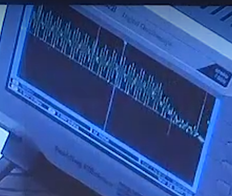
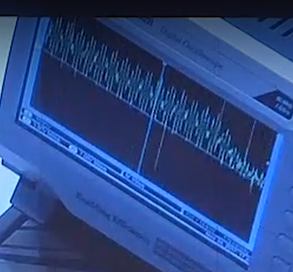
Here is the 2nd ignition pulse, which did start the reactor. Note the massive spikes that occurred on the right side of the screen that did not occur with the 1st ignition pulse. I believe this adds to the data that when the reactor is running, it is outputting AC electrical energy.
https://uploads.disquscdn.c...
Here are other ignition pulses that occurred during the 1 hour run. Note they are very much cleaner, probably because the reactor was hot. Also take note the 100kHz signal amplitude is not stable right after the ignition pulse, which to me says the 100kHz signal is being generated by the reactor. I also suspect the control box monitors the level and maybe cross over data to deyermine when the reaction needs a small kick along pulse, which we see as the smaller than start pulses that are fast, like spikes and go negative and off screen at the top.
https://uploads.disquscdn.c...
https://uploads.disquscdn.c...
https://uploads.disquscdn.c...
Here s what may be happening:
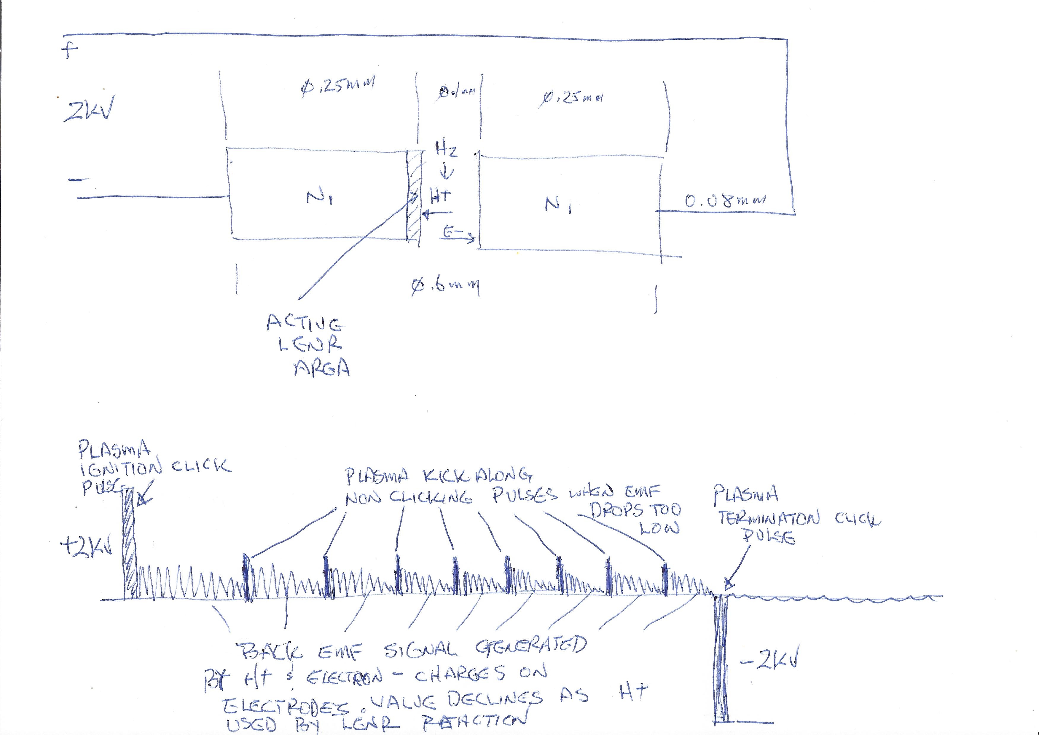
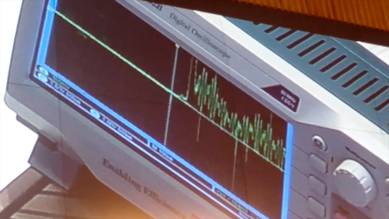
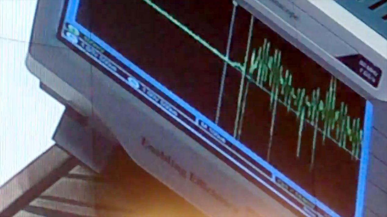
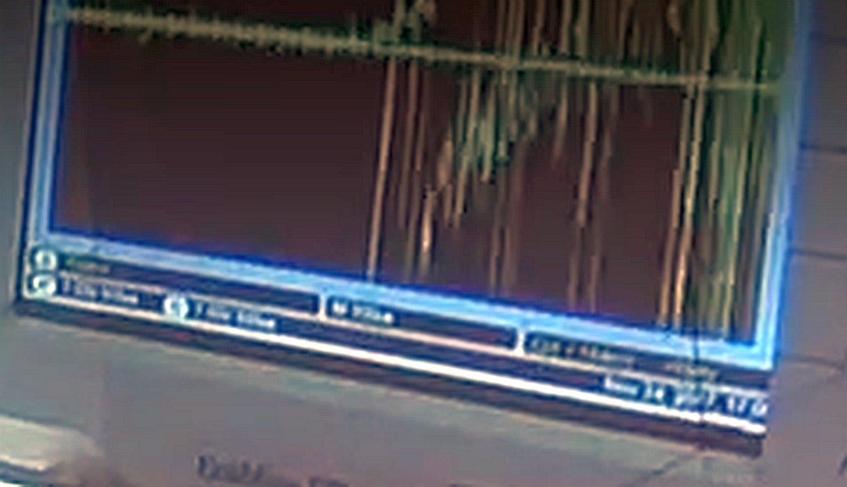
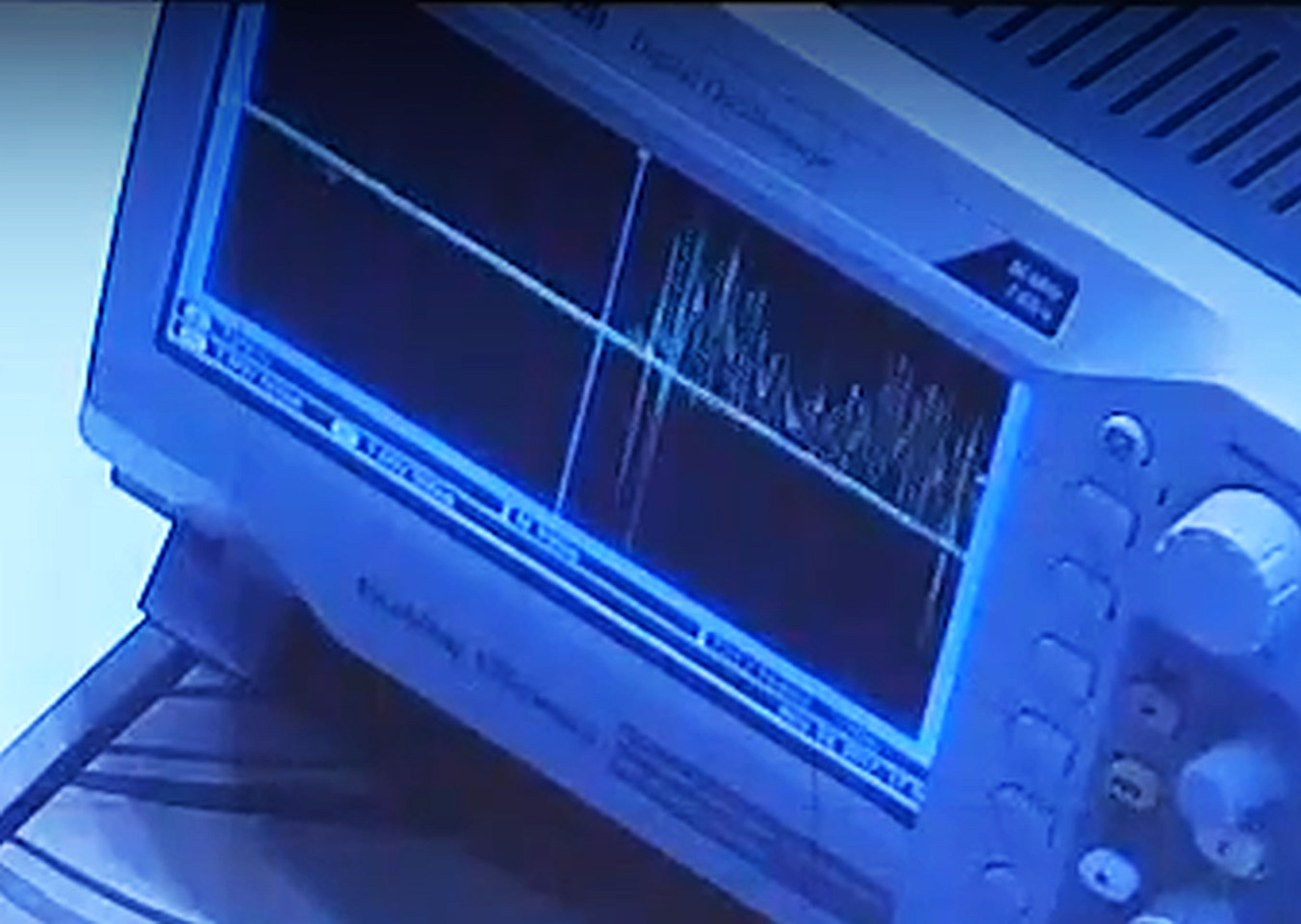
Compare photos [2:] of the demo oscilloscope during QX startup to [1:]. To my mind, Fig 4 and the photos have the same general form. The core of the paper is an equation, presented as (1) : i(t) = C.dV/dt + V.dC/dt
The QX and controller appear to be, in essence, a series RLC electrical circuit that oscillates at a near resonant frequency in normal operation. The second term of the equation shows the 'C' in the 'RLC' varying in time and this second term is always negative because V and dC/dt are always of opposite sign.
If C.dV/dt is low positive and V.dC/dt is large negative with positive V, then the value of i(t) can be negative whilst V is positive. The AC current then flows in the opposite direction to the voltage which is a definition of NDR (Negative Differential Resistance). The double layer inputs AC electrical energy into the external circuit.
The addition of a sufficient positive bias current to the circuit stops i(t) ever going negative in normal operation of the QX.
[1:] http://vant.kipt.kharkov.ua...
These equations are solved by numerical methods. Fig. 4 shows the dynamics of the double layer current capacitive component i (t) C (curve 1) and the active voltage U (t) a (curve 2) in the high-current pulsed discharge.
Fig. 4. The dynamics of the double layer current capacitive component i (t) C (1) and the active voltage U (t) a (2) of the high-current pulsed discharge
[2:] http://e-catworld.com/2017/...
Photos of oscilloscope during QX startup
What the QX reactors do self generate is the light that they all produce. When the RF is switched off the light of the plasma stays on.
Regarding:"Also take note the 100kHz signal amplitude is not stable right after the ignition pulse, which to me says the 100kHz signal is being generated by the reactor. "
I remember the waveform produced by the controller used to stimulate the LENR reaction depicted by the frequency and harmonic analyzer in the Lugano demo was a RF shaped complex sine waveform.
It is possible that the QX reaction sometimes produces a RF signal that can interact and combine with the controller produced signal.
Also...since there were three QX reactors in operation, if each QX produced its own RF signal then the combined RF signal would be very complex, continually changing and random.
...if they're not adapting to each other, in resonance.
If the QX produces RF, then when the 3 second "on" portion of the controller cycle stops, then the RF signal would continue during the 4 second "off" self sustain portion of the controller cycle. What remains "on" is the light produced by the plasma. That light could be the sync up signal.
Hi Axil,
There is no energy production during the 4 sec OFF periods. The plasma and reaction stops.
Didn't Rossi state that the reaction goes into self sustain mode when the input energy stops? Rossi said that there was a 3/7 factor in the COP calculation? Or am I not remembering the demo correctly?
Hi Axil,
It was 3 sec on and 4 sec off.
Self sustain occurred after 1st bright ignition pulse at the start of each 3 sec on period. So 3 seconds of self sustain, plus I suggest a few smaller voltage and shorter duration kick along self sustain helper pulses.
https://youtu.be/Nz0Z94Ix-k...
Ar 2:17:30 give or take of the demo, the spectrometer readings were displayed on the laptop. The light spectrum on the laptop persisted for the entire 7 second cycle for a few cycles at least. Check it out I could be wrong.
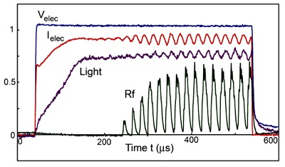
The close fit of the oscillation frequency on the demo oscilloscope and the frequency on Fig.5.[1:] is not coincidental IMHO. The beat frequency on the oscilloscope is the product of the Rf frequency of the fireball and the output frequency of the controller. The 'beat' is the 'cat'[controller] and 'mouse'[fireball] in operation.
1: http://www.physics.ucla.edu...
Electrons from the ambient plasma are accelerated into the fireball by the double layer potential drop (approx. equal to the ionization potential). The beam-plasma system inside the fireball excites electron plasma waves. …
https://uploads.disquscdn.c...
Fig. 5. Waveforms of the electrode voltage, current , light and rf emissions for a pulsating fireball. The rf modulation arises from the density oscillations and the narrow receiver bandwidth.
Nice find. Note that the oscillation frequency is about 50kHz -- similar to that observed in the QX waveforms. Also, other graphs show current pulses -- similar to the pulses seen occurring in the QX waveform and maybe coincident with the pinpoints of light (See Frank's description of the plasma below -- "5. One or two tiny pinpricks of light floating slowly within the plasma").
Hi GADAB,
Welcome to the puzzle Rossi has set us and discussion on how to solve it.
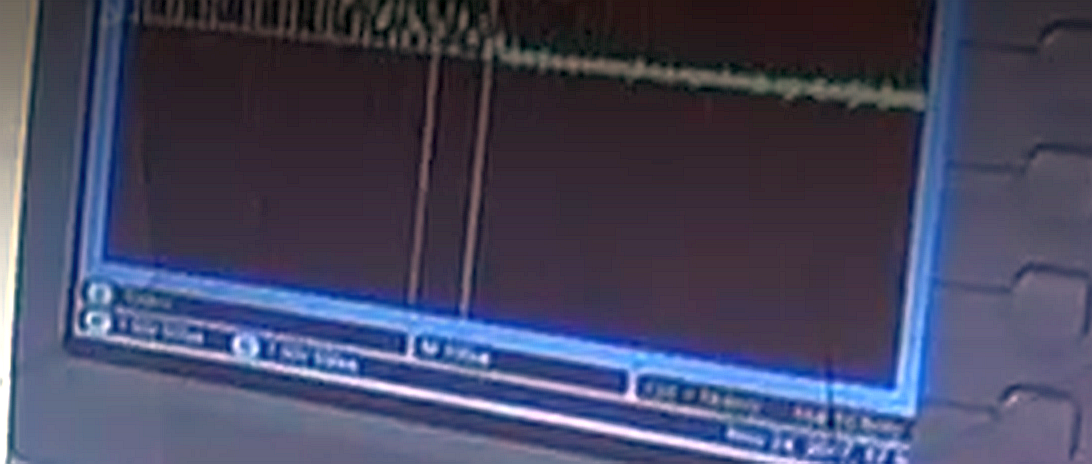
To add to the discussion of what comes out of the QX reactor I submit these images showing the 100kHz current waveform decays just before the plasma turns off, which is not what it would do if it was generated by the control box.
https://uploads.disquscdn.c...
I think this and Andreas Moraitis points below could well be right on the point.
I was also wondering about acoustic resonance. The acoustic wave length of 100Hz could be quite close to the 6mm size of the reaction zone gap. Depending on the Pressure and Temperature and consequently the speed of sound in the device. I think at air pressure and normal temperatures it is about 3mm for example. Obviously the actual pressure and temperature in the device could be different.
Andreas is also right to mention that since we are talking a plasma we could be talking about other Magnetohydrodynamic (MHD)oscillations than normal acoustic oscillations including ion oscillations, Alfvén waves, Larmor waves etc.
One thing intresting about this if those 100Hz oscillations are related to the acoustic conditions in the device is that changes in frequency would indicate changes in speed of sound in the device which could give very fast feed back on the pressure and temperature inside the device. And perhaps the intensity and shape of the oscillations rate of change could give even more data especially if they are passed through a Fast Fourrier Transform ( FFT) to extract detailed frequency information. This could be very important fast and responsive information regarding the conditions in the device if it needs to be maintained in a very precise conditions such as temperature and pressure to work. And could also give good feedback when those conditions start to change or become exhausted.
Regarding the Oscillations they look like Beats between two or three sources at close to 100 kHz but separated by about 10 kHz to me. This could also be consistent with the control of the device.
Andrea Rossi often talked about resonance in his devices. I think he could be using this to amplify a particular condition in the device he needs for self sustain. It could also be that by tuning the three Ecat-QX's to resonate together it supports these resonances in like a tuning fork.
The tuning like effect at the beginning might be an attempt to get the three Ecat QX's in phase and in resonance with each other. Perhaps once in phase like this the three eCats support each other in a kind of self sustain. Is this why he uses three devices?
On one hand you might want a resonance to operate the device at the edge so to speak to stimulate something in the device but on the other hand usually in control theory you want to avoid these kinds of resonances as they can lead to runaway behaviour, structural breakdown and/or loss of control. Perhaps this is why we see Beats, as the device is being maintained in a controlled resonance but with out being aloud to runaway in full resonance.
FFT analysis and Processing the modulation wave form of the beats might also give information about how the devices are working together, if one is getting out of tune etc.
Of course all this is completely speculative but I think it could fit well.
If there is an acoustic/MHD wave counter part to the 100 kHz signal I wonder if the bright spot seen by Frank are artefacts of a standing wave in the device.
I do have some reserve about this approach though. Recently Andrea Rossi mentioned on his blog that the device does not produce an acoustic output. so maybe the idea doesn't hold after all. But I think it could be he was talking about outside the device rather than Acoustic or MHD shocks or waves inside the device.
Hi Stephen,
I think the beat is because there are slightly different freq generated in each of the 3 parallel QX reactors plasma.
And yes the acoustic resonance could be greater than air's 3mm at that freq.
Plus yes. Modern microcontrollers have more than enough fire power to do a high res analysis of every part of the plasma generated waveform.
Would suspect there is more than enough data recoverable from the signal to reveal a lot of real time operational data about the status of the reaction.
BTW in the 1 year ECats there was circuitry in the control boxes to monitor EM fields generated by the reaction and report that info, in real time, back to the main control computer. I have always believed the QX control system would be similar to that used before.
I suspect the smaller spiky pulses are kick along plasma sustain pulses when the controller determines the plasma needs a little help to maintain a constant reaction rate.
My impression is given what we currently know there are two possible types of locations for the source of energy and LENR.
1. Is in the plasma it self and that the very specific control of that plasma is optimizing the environmental conditions at particular locations in that plasma for it to occur. (Perhaps this would fit his ideas about resonance and particles production)
2. The LENR is occurring in the Nickel Rod surfaces and generating high energy ions that are later thermalised in the plasma.
To put my speculation hat on...
My personal preference is option 2. In this case we would need the Nickel Rods to be kept at particular temperature ranges where Hydrogen sorbtion processes can still occur. This might account for their separation and size to some extent to allow them to maintain a lower temperature than the plasma. I think the LENR process it self causes the ions to shake off the nickel crystals so to speek with very high kinetic energy (like water from a wet dog). For this to occur for each individual LENR event this might require um crystals and/or nano structures on the surface to replace what the former powder was doing. A too small structure would over heat and melt. A too large structure would not pass enough kinetic energy to all the hydrogen ions in the surface or allow the energy to be conducted away before it did so. The nano structuring on surface of the structure could also impact the density of hydrogen sorbtion and path of flight on ejection.
Some of the high velocity ions produced may support further LENR interactions either directly or indirectly through X-ray stimulation, other plasmonic effects or something else but other ions would maybe released into the electric field at high KE.
I think the thermalisation of the plasma is occurring in the dense parts of the plasma through interaction with the high energy ions possibly the bright spots mentioned by Frank are those dense regions if they are indeed due to standing waves as I was speculating
This wouldn’t explain the underlying LENR process itself, how it was triggered or how its energy us translated with in a nano particles to the adsorbed ions but it might explain how the machine uses it if ions are generated that way.
You might have hit upon the proper mechanism for LENR reaction generation in the QX. The light produced by the central plasma ball might be a stimulator of the reaction and not where the LENR reaction is actually occurring. The RF wave feed by the controller fluxuates between a minimum to a maximum at 100 KHZ. This light production stimulus could produce a light source that flickers like the light from a strobe bulb.
Like the laser from the Holmlid experiments, the light triggers the LENR reaction. Also, in the HID bulb, the light is produced by a square wave that produces light only when the square wave is at maximum.
This LENR stimulation effect is a result of the AC KERR effect.
The LENR reaction might be centered in the electrodes that you pointed out and/or the pinpoint ball lightning spots that are seen floating around inside the QX gas envelope.
If this hypothesis is true, than all the measurements done by Rossi are invalid including the COP calculations. Also, I would be disappointed in Rossi if he knows about this QX mechanism and is covering this IP feature up to deceive the competition.
I’m not fully into it yet there is still a lot to understand but I don’t think it invalidates Rossi at all. If these bright spots are where the plasma is thermalised in a standing wave or even a plasma equivalent the thermal plasma itself would still extend the whole plasma I think. It would just be thermalising the high kinetic energy ions in these dense or otherwise strongly interactive spots. Once thermalised they would extend through the whole plasma.
But I am guessing.
It’s a good idea though that you mention that maybe something about these spots is stimulating the LENR elsewhere in the rods. For sure we seem to have some degree of feed back and control of the LENR it self.. I dont think my speculations explain that part yet.
There is little doubt about the thermal output of the E-Cat QX in my mind after the Calorimetry and the current explanation of the Black Body spectrum fits well with that. I personally have no doubts on that part.
I suppose there could be a combination too. Such as Lithium and Hydrogen ions thrown off the surface of the Nickel by LENR that then interact in the bright spots generating Helium there as per his classic earlier descriptions. That might explain the heating of the plasma if normal thermalisation of high energy ions was not sufficient.
Regarding control...
The frequency of the RF controls the power level of the LENR reaction. The higher the RF frequency applied, the higher the LENR power output. The situation is like a strobe light. The faster that is fires, the more light that it produces.
The electrodes do not melt even with the plasma so close to the electrodes because the plasma is cold...that hydrogen plasma does not produce all that heat.
It’s very likely the plasma in contact with the electrodes is much lower than that in the reaction zone as you say. This is in common with all plasma lamps I think (except those that maybe use a thermal source). I think the only plasma in touch with the electrodes is the high energy non thermal ion or electron emission. But those electrodes should be separated by sufficient distance from the thermal plasma that 1/r^2 results in the temperature at that point being low enough (taking into account thermal conduction as well) not to melt the electrodes at least but also maybe low enough for hydrogen adsorption to still occur (but maybe hot enough for Lithium adsorption too).
I agree though it would be really interesting to characterize the thermal behavior and spectra in more resolution especially the bright spots. I think that’s maybe your point? At least I think it would better clarify yours and others ideas about the active mechanism if that kind of measurement was possible.
We are all just guessing what those bright spots could be. It would be really interesting to see if there is a particular spectrum signature there as you have mentioned before. Or if there is a particularly strong Helium line for example.
But I guess we will have to wait now until production to really be sure about this. From a scientific point of view I’m really curious.
That was also my first thought when I saw it. However, the ‘decay’ of the voltage (measured across the 1 ohm resistor, not the reactor) could as well result from rising plasma resistance, caused by de-ionization of the plasma when it cooled down.
If the 100 kHz signal comes from the reactor, it might have its origin in (1) acoustic resonance or (2) ion oscillations. For electron oscillations, the frequency seems to be too low. But surely, we do not know what happened beyond the limit of the oscilloscope.
Interesting. Does someone know what are the frequencies involved?
Someone said the scope was set to 100uS/div which gives something around 83kHz.
A close match is 83.03kHz being modulated by 9.5kHz
83.03kHz * ABS(9.5kHz)
Hi DaPhys,
Scope time base was 100 usec per division or 1 msec side to side.
Freq estimated to be 100 kHz.
The NASA patent application claim to be able to cause a short term shutdown of the deuterium's Coulomb barrier, so to allow deuterium fusion to occur at much lower energies than normal.
https://uploads.disquscdn.c...
Then the deuterium fusion triggers fission in the deuterated high Z or high proton count, host matrix.
Seems they suggest a 4 stage process.
Load deuterium into the host high Z matrix, ie deuterate it.
Screen the Coulomb force in the deuterium for a short period.
Initiate deuterium fusion.
This fusion triggers fission in the high Z host matrix.